
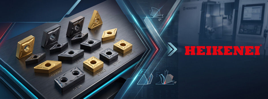
Breaking down how to navigate lines from CF01 to CF48 and flat geometries CF110–CF111.
1. Finishing and Light Machining (CF01 – CF21)
The primary goal at this stage is smooth, vibration-free cutting and clean evacuation of thin chips.
- For steels and soft alloys (CF01, CF04, CF16): geometries with a high rake angle and sharp cutting edge reduce cutting forces and prevent built-up edge when machining gummy materials.
- For heat-resistant superalloys and titanium (CF05, CF12, CF20): a smooth chipbreaker radius eliminates heat concentration and ensures chip control even at shallow depths of cut.
- Doubled feed rate with Wiper (CF15): the wiper edge allows you to double the feed rate while maintaining the required surface roughness.
- High precision (CNGG, DNGG, TNGG series): ground periphery (tolerance class G) guarantees stable dimensions on finishing passes.
2. Semi-Finishing and General Machining (CF22 – CF34)
The baseline range for most turning operations requiring a reliable balance between edge strength and chip control.
- Universal solutions for steel (CF22, CF27, CF33): these geometries excel in longitudinal turning, profiling, and shoulder machining at varying depths of cut.
- For stainless steel (CF23, CF26, CF31): optimized nose geometry minimizes plastic deformation of the tool tip and prevents crater wear.
- Semi-finishing Wiper (CF30): insert with an enlarged chip pocket designed for high-productivity turning without chip jamming.
3. Roughing, Scale, and Interrupted Cuts (CF35 – CF46, CF110 – CF111)
Here, chipping resistance and the ability to handle forgings, castings, and hard scale take center stage.
- Interrupted cuts and scale (CF35, CF37, CF39): a reinforced, wide T-land effectively withstands cyclical impacts and uneven stock allowances.
- Heavy roughing (CNMM, SNMM series — CF41, CF44, CF46): robust single-sided geometries with a wave-pattern chipbreaker and wide land for machining at elevated feed rates and large depths of cut.
- Cast iron machining (CF47, CF48, CF110, CF111): flat-top inserts without chipbreakers (CNMA, DNMA, SNMN). Cast iron produces discontinuous chips, so solid carbide directly beneath the cutting edge provides maximum protection against chipping.
Quick Guide to Chipbreaker Selection
Finishing and precision passes (CF01–CF09, CF15 Wiper):
- When to choose: minimal stock allowance, thin-walled parts, and setups prone to vibration.
- Result: smooth, shock-free cutting, consistent breaking of thin chips, and mirror-like surface quality without material adhesion.
Universal and semi-finishing tasks (CF22, CF23, CF30 Wiper):
- When to choose: general turning, longitudinal profiling passes, and variable depths of cut.
- Result: balanced nose toughness, protection against thermomechanical wear, and high productivity without chip groove clogging.
Roughing, scale, and interrupted cuts (CF37, CF39, CF41, CF46):
- When to choose: forgings, weldments, castings, and heavy material removal at maximum cutting parameters.
- Result: maximum edge rigidity via an extended land (up to 0.68 mm) and protection against chipping under severe cyclical shock loads.
Turning grey and ductile cast iron (CF47, CF48, CF110, CF111):
- When to choose: uneven stock allowances and machining of cast iron components.
- Result: maximum carbide cross-section in flat-top geometries (non-chipbreaker), engineered specifically for discontinuous cast iron chip formation.
Cutting corners on edge prep doesn't always pay off. In our next article, we will explore the operations where switching to positive inserts (CCMT, DCMT, VBMT) is not just justified, but essential to save costly workpieces from vibration and scrap.