

What the indicator actually shows
When the tip comes into contact with the surface of the part, the movement is transmitted to the pointer mechanism. If the part rotates, the pointer deflects between the minimum and maximum values. The difference between these extremes can be used to assess runout — but only if such a scheme is provided for in the drawing and the inspection method.
At the same time, the reading includes not only the geometry of the surface being monitored. It is influenced by:
- the error in the part’s base alignment;
- the condition of the centers or spindle;
- deformation and play of the fixture;
- vibration;
- non‑perpendicularity of the measuring rod;
- surface contamination;
- indicator’s inherent error.
That is why the indicator should be selected and used as an element of the measuring system, not as a standalone device.
Radial and end runout are different tasks
When monitoring radial runout, the tip is placed on the cylindrical surface, and the direction of the measuring rod is aligned with the normal to the surface at the point of contact. The part is rotated relative to the specified base, and the change in the reading is recorded.
When monitoring end runout, the tip contacts the end surface at the set radius. The measuring direction must correspond to the geometry of the surface being inspected.
It is important to distinguish between circular runout and full runout — these are different geometric requirements. For full runout, the procedure may involve moving the contact along the surface while the part is rotating. The phrase “check runout with an indicator” is not sufficient to develop a methodology: you need to know the tolerance designation on the drawing, the datum, and the required control scheme.
Why runout cannot be automatically equated with ovality or eccentricity
If the pointer changes position when the shaft rotates, this does not prove that the shaft has only one specific type of geometric deviation. The reading may be due to a shift of the axis relative to the datum, a surface shape deviation, an installation error, or a combination of factors. Based on a single runout reading, it is impossible to determine roundness, cylindricity, or the position of the axis without an additional method.
The division value is not a synonym for accuracy
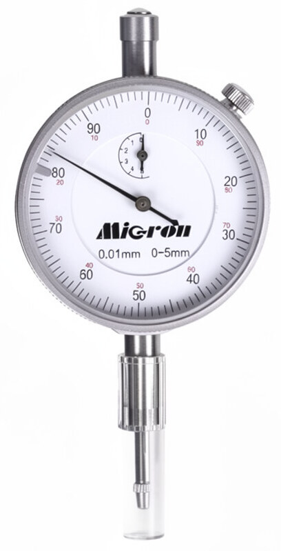
For IC indicators, the common division value is 0.01 mm. This is the size of one scale division, but not the limit of the permissible error of the device. For each type of indicator, metrological characteristics are standardized, including permissible errors in different parts of the range.
Therefore, the selection cannot be made according to the rule "a tolerance of 0.02 mm means that the 0.01 mm indicator is sufficient". It is necessary to evaluate at least:
- the division price;
- measuring range;
- the permissible error of a specific indicator;
- variation of readings;
- measuring force;
- contribution of the rack, base and fixtures;
- the permissible error of the entire accepted methodology.
For example, with a runout tolerance of 0.05 mm, a division value of 0.01 mm yields five divisions for the tolerance value — this characterizes the readability of the scale, but in itself does not confirm the metrological suitability of the method.
|
|
|
|
When a finer reading is needed
Indicators with a reading of 0.001 mm are used in tasks where it is necessary to record minimal movements. However, installing such an indicator on a conventional flexible magnetic stand does not turn the system into a micrometer‑level measuring circuit.
With this kind of counting, the following become particularly noticeable:
- elastic deformation of the strut arm;
- displacement of the magnetic base;
- equipment vibration;
- contamination of the base surface;
- temperature movements;
- joint play.
Switching to a finer scale requires checking all the equipment — otherwise, an extra decimal place creates a false impression of accuracy.
Measurement range and preload
A large overall range is not always required for monitoring runout. The main task is to ensure the working position of the tip and register the expected change without the mechanism exceeding its travel limits.
Before the inspection, a working movement of the rod is created — the so‑called preload. Its value depends on the indicator range and the manufacturer’s instructions; a universal value in millimeters cannot be set for all models. An excessively large range also does not mean higher accuracy — these parameters are evaluated separately.
Measuring force
The indicator tip exerts force on the part. For rigid shafts, its influence is usually negligible, but for thin walls, sheet parts, flexible plates, and low‑rigidity elements, the deformation caused by the measuring force may be comparable to the controlled tolerance. For such parts, it is necessary to check the measuring force according to the documentation and assess the possible deformation.
Proper installation
The indicator is secured in a stand or tripod so that the connections do not move during the inspection. The lever extension is made minimal — the longer and more complex the lever system, the greater its elastic compliance.
After placing the tip at the required point, the working position of the rod is established; the scale can be set to the zero mark for convenience. This is setting the initial reading, not verification. Then the part is slowly rotated relative to the specified base, and the maximum and minimum readings are recorded. The result is repeated to check reproducibility. If, after a full rotation, the initial position changes noticeably without any change to the part, the measuring system should be checked first.
Rod Direction
The indicator records the displacement component along its measuring axis. If the rod axis is positioned at a noticeable angle to the required direction, the measurement includes a geometric component associated with this angle. Therefore, with a plunger indicator, the direction is sought to be aligned with the normal to the surface being measured. For hard-to-reach areas, lever-and-tooth designs are used — their kinematics differ, and the requirements for the lever position should be taken from the documentation of the specific measuring instrument.
Mounting: by the sleeve or by the eyelet
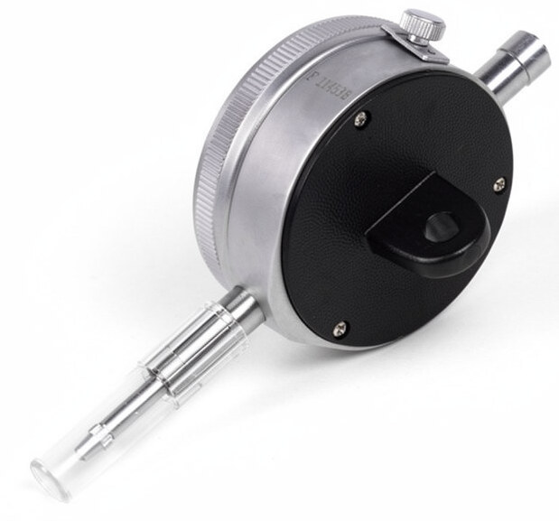
The indicator design may include mounting via an attachment sleeve or via an eyelet on the rear cover. When selecting, it is necessary to check compatibility with the existing stand. The fact that the indicator can be physically secured does not mean that the mounting provides the required rigidity — the connection must maintain its position throughout the entire operation.
Work in the workshop
For measurements taken directly on the machine, vibration, contamination, and the condition of the surface on which the stand is installed should be taken into account. The magnetic base requires a clean ferromagnetic base: a layer of chips, paint, corrosion, or a small contact area reduces the actual rigidity of the mount.
You cannot install the stand on an element that moves relative to the base relative to which the runout needs to be determined. If the inspection is carried out with the equipment running, safety requirements and the approved technological procedure must be observed. In many cases, measurements are taken while manually or slowly rotating the part, rather than in the machine’s operating mode.
Verification and the State Register
For measurements in the field of state regulation aimed at ensuring the uniformity of measurements, the metrological status of a specific indicator and the presence of an active verification are checked. The presence of a type in the State Register refers to the type of measuring instrument, while verification refers to a specific instance. However, verifying an indicator does not automatically confirm the suitability of the entire control scheme: the stand, the base, the fixture, and the methodology still contribute to the result.
Typical mistakes when choosing
- Choosing an indicator based solely on the division value.
- Considering the reading as a direct measurement of geometric deviation without taking the base into account.
- Use a 0.001 mm indicator on insufficiently rigid tooling without checking reproducibility.
- Select the maximum range instead of analyzing the working stroke.
- Do not take into account the measuring force on low‑rigidity parts.
- Install the measuring rod at an arbitrary angle.
- Consider any change in the needle position when the part is rotated as evidence of eccentricity or ovality.
A dial indicator for monitoring runout is not selected separately, but as part of a measuring system. Appropriate gradation and metrological characteristics, a sufficient operating range, the correct measuring force, and compatibility with the stand are required. When performing the inspection, the part’s base, the rigidity of the mounting, and the measurement direction become decisive factors. That is why an indicator with a finer scale does not always provide a more reliable result — its capabilities must be supported by the entire measurement circuit.