Types of tool wear during turning
Types of tool wear during turning, defective parts and ways to eliminate them
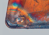
FORMATION OF A GROWTH ON THE CUTTING EDGE

Recommendations:
-
change (increase) cutting speed
-
change (increase) the feed
-
apply coated types of hard alloy
-
apply a different cutting geometry
-
apply a coolant with a higher action against the formation of a build-up (in its absence, refuse cooling)
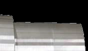
WEAR ON THE BACK SURFACE

Recommendations:
-
apply a more wear-resistant type of hard alloy
-
reduce the cutting speed
-
increase the feed (if the feed is less than 0.1 mm/tooth)
-
apply coolant or increase the cooling intensity
THE HOLE ON THE FRONT SURFACE
Recommendations:
-
apply a more wear-resistant type of hard alloy
-
apply a hard alloy with a coating, first of all, MT CVD
-
reduce the cutting speed - apply a different, more positive type of cutting geometry
-
apply coolant or increase the cooling intensity;
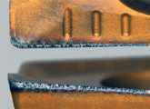
THE GROOVE ON THE AUXILIARY CUTTING EDGE

Recommendations:
-
apply a coated hard alloy or a more wear-resistant type of hard alloy, if conditions allow
-
apply SMP with a coating containing Al2O3
-
apply coolant or increase the cooling intensity
-
reduce the cutting speed;
PLASTIC DEFORMATION OF THE VERTEX;

Recommendations:
-
apply a more wear-resistant type of hard alloy;
-
reduce the cutting speed
-
reduce the feed
-
apply coolant or increase the cooling intensity
-
apply a NSR with a large radius of rounding the vertex
-
apply a SMP with a large angle at the top;
THE GROOVE ON THE MAIN CUTTING EDGE

Recommendations:
- apply a hard alloy with a coating or a more wear-resistant type of hard alloy, if conditions allow
-
apply SMP with a coating containing Al2O3
-
choose a tool with a smaller angle in the plan
-
process with variable cutting depth (along the cone)
PAINTING OF THE CUTTING EDGE;

Recommendations:
-
apply a more viscous type of hard alloy;
-
choose less intensive cutting conditions
-
apply a different cutting geometry
-
when cutting in, reduce the feed
-
change the way the tool enters and exits when cutting;
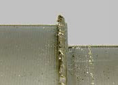
DESTRUCTION OF THE CUTTING EDGE (OUTSIDE THE CUTTING AREA)

Recommendations:
-
change the feed
-
choose a tool with a different main angle in the plan;
-
apply a different cutting geometry (a different chip breaker)
-
apply a more viscous type of hard alloy;
THERMAL CRACKS
Recommendations:
-
refuse liquid cooling (air can be used to eliminate chips from the cutting area)
-
choose a more viscous SMP material
-
reduce the cutting speed;
FATIGUE CRACKS;

Recommendations:
-
apply a more viscous type of hard alloy;
-
will change the way the tool enters and exits the workpiece
-
change the embedding conditions
-
apply a different type of cutting geometry or a different shape of the NSR (...T, ....S, ....K, ....P)
PAINTING THE CUTTING EDGE OR THE TOP OF THE TOOL;

Recommendations:
-
apply a more viscous type of hard alloy;
-
choose less intensive cutting conditions (reduce feed and depth)
-
apply a NSR with a large radius of rounding the vertex
-
apply the SMP with a large angle at the top
-
apply a different cutting geometry (a different chip breaker)
-
stabilize the cutting edge (cutting edge)
-
reduce the feed when cutting
BURR FORMATION;
Recommendations:
-
apply SMP with a sharp cutting edge;
-
apply SMP with positive geometry
-
apply a tool with a smaller angle in the plan;
INACCURACY OF THE SIZE AND SHAPE OF THE WORKPIECE;
Recommendations:
-
select СМП with sufficient wear resistance;
-
check the reliability of fixing the workpiece
-
check the reliability of fixing the tool (reduce overhang or eliminate imbalance)
-
choose the appropriate size of the allowance for processing;
UNSATISFACTORY CHIP FORMATION;

Recommendations:
-
change the feed and cutting depth;
-
choose a more suitable geometry
-
change the embedding conditions;
GENERAL RECOMMENDATIONS;
Control of the correct fit of the NSR in the socket. Before installing a new SMP or changing the cutting edge, it is necessary to clean the seat, check its condition - there is no damage to the wedge and the backing plate.
Control and repair of fasteners. It is important to control the fasteners themselves: the angle lever, screw, tack or clamping wedge. Only undamaged elements should be used for fastening, in case of their replacement, only spare parts that are listed in the catalog of this tool should be used. Regularly lubricate the thread and the conical bearing surface of the screws with grease resistant to elevated temperatures, for example, Molykote G. When mounting or disassembling, use only screwdrivers and keys specified in the catalog and recommended by the tool manufacturer. It is necessary to tighten all screws using a torque wrench.
Pinning control. When fixing the NSR, it is necessary to check its tight fit over the entire support surface and the emphasis - in the radial and axial directions. Fixed SMPS and tools must always be clean and undamaged.
Sandvik materials were used, Pramet.