Formulas and definitions for milling
Here are useful formulas and definitions necessary for milling: the processing process, milling cutters, milling methods, etc. The ability to correctly calculate the cutting speed, feed to the tooth and the rate of removal of metal is crucial to obtain good results when performing any milling operation.
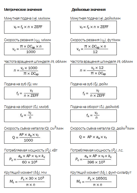
| Parameter | Value | Metric units | Inch units |
| ae | Milling width | mm | inch |
| ap | Axial cutting depth | mm | inch |
| DCap | Cutting diameter at cutting depth ap | mm | inch |
| Dm | Processed diameter (part diameter) | mm | inch |
| fz | Feeding on the tooth | mm | inch |
| fn | Submission for turnover | mm/rev | inch |
| N | Spindle speed | rpm | rpm |
| vc | Cutting speed | m/min | ft/min |
| ve | Effective cutting speed | mm/min | inch/min |
| vf | Minute feed | mm/min | inch/min |
| zc | Effective number of teeth | pc. | pc. |
| hex | Maximum chip thickness | mm | inch |
| hm | Average chip thickness | mm | inch |
| kc | Specific cutting force | N/mm2 | N/in2 |
| Pc | Power consumption | kW | hp |
| Mc | Torque | N·m | pound-force/foot |
| Q | Metal removal rate | cm3/min | in3/min |
| KAPR | The main angle in the plan | hail |
|
| PSIR | Angle in plan (in.) |
|
hail |
| BD | Case diameter | mm | inch |
| DC | Cutting diameter | mm | inch |
| LU | Working length | mm | inch |
Basic definitions
-
Cutting speed, vc
Circumferential speed of movement of the cutting edge relative to the workpiece.
-
Effective or actual cutting speed, ve
Circumferential speed at the effective cutting diameter (DCap). This value is necessary to determine the cutting modes at the actual cutting depth (ap). This is especially important when using milling cutters with round plates, milling cutters with a spherical end and all milling cutters with a large radius at the top, as well as milling cutters with a main angle in the plan of less than 90 degrees.
-
Spindle speed, n
The number of revolutions of the milling cutter fixed in the spindle, performed per minute. This parameter is related to the characteristics of the machine and is calculated based on the recommended cutting speed for this operation.
-
Feed per tooth, fz
Parameter for calculating the minute feed. The feed to the tooth is determined based on the recommended values of the maximum chip thickness.
-
Feed per turn, fn
An auxiliary parameter that shows how far the tool moves in one complete revolution. It is measured in mm/rev and is used to calculate the minute feed and is often the determining parameter for finishing.
-
Minute feed, vf
It is also called the feed rate. This is the speed of movement of the tool relative to the workpiece, expressed in the distance traveled per unit of time. It is related to the feed to the tooth and the number of teeth of the cutter. The number of teeth of the cutter (zn) may exceed the effective number of teeth (zc), that is, the number of teeth in cutting, which is used to determine the minute feed. The feed per revolution (fn) in mm/rev (inch/rev) is used to calculate the minute feed and is often the determining parameter for finishing.
-
Maximum chip thickness, hex
This parameter is related to the feed to the tooth (fz), the milling width (ae) and the main angle in the plan (kr). Chip thickness is an important criterion when choosing a feed to the tooth to ensure the highest minute feed.


-
Average chip thickness, hm
A useful parameter for determining the specific cutting force used to calculate power consumption.
-
Metal removal rate, Q (cm3/min)
The volume of the removed metal in cubic millimeters per minute (in3/min). It is determined based on the depth and width of cutting and feeding.
-
Specific cutting force, kct
The material constant used to calculate the power and expressed in N/mm2
-
Processing time, Tc (min)
The ratio of the processed length (lm) to the minute feed (vf).
-
Power consumption, Pc and efficiency, nmt
Machine characteristics that help to calculate the power consumption and evaluate the possibility of using the tool on this equipment for this processing operation.
Milling methods
-
Linear embedding
Simultaneous translational movement of the tool in the axial and radial directions.
-
Circular interpolation
Moving the tool along a circular path at a constant z coordinate.
-
Circular milling with embedding at an angle
Moving the tool along a circular path with embedding (screw interpolation).
-
Milling in one plane
Milling with a constant z coordinate.
-
Point contact milling
Shallow radial embedding by cutters with round plates or a spherical end, in which the cutting zone is shifted from the center of the tool.
-
Profile milling
Formation of repetitive protrusions during profile surface treatment with a spherical tool.
Formulas for different types of milling cutters
Formulas for cutters with a straight cutting edge


Helical interpolation (on 3 axes) or circular interpolation (on 2 axes) - internal processing
Formulas
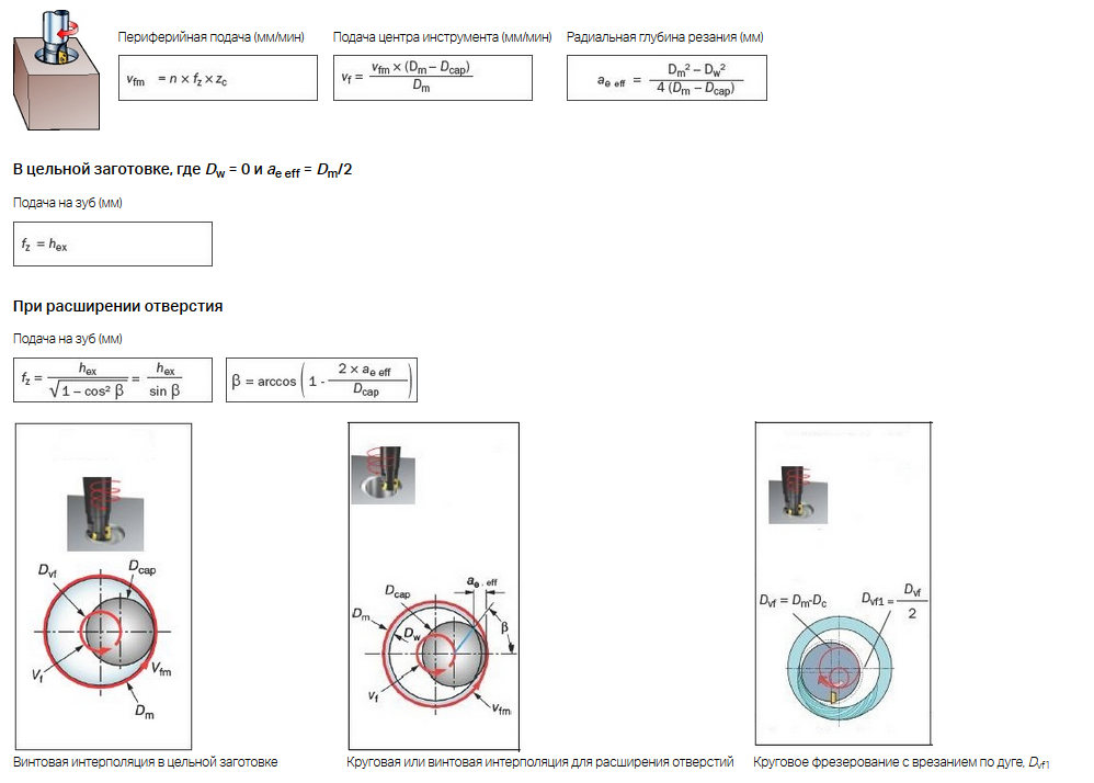
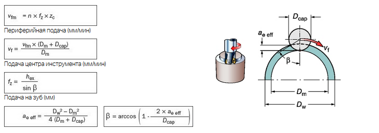
Helical interpolation (on 3 axes) or circular interpolation (on 2 axes) - external processing
Formulas
Parameters of milling plates
Plate geometry
Important parameters of the geometry of the cutting edge of the plate are:
- main front angle (γ)
- sharpening angle (β)
Macrogeometry is designed to work in light, medium and heavy conditions.
- The geometry L (for light conditions) has a more positive but weaker edge (large angle γ, small angle β)
- The geometry H (for heavy conditions) has a stronger but less positive edge (small angle γ, large angle β)
Macrogeometry affects many cutting parameters. A plate with a strong edge can work under heavy loads, but at the same time creates large cutting forces, consumes more energy and emits more heat. Optimized geometries have special letter designations according to ISO classification.
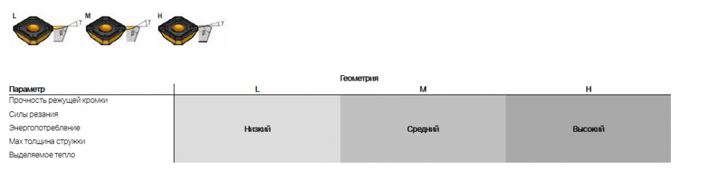
Plate top construction
The most important element of the cutting edge for obtaining the required quality of the treated surface is a parallel chamfer bs1 or, if applicable, a convex chamfer Wiper bs2, or the radius at the vertex rε.

Definitions for milling cutters
-
The main angle in the plan (kr), deg.
The main angle in the plan (kr) is the main geometric parameter of the cutter, since it determines the direction of the cutting force and the chip thickness.
-
Milling cutter diameter (Dc), mm
The diameter of the cutter (Dc) is measured through the point (PK) where the main cutting edge intersects with the parallel chamfer.
The most informative parameter is (Dcap) - the effective cutting diameter at the current cutting depth (ap), it is used to calculate the speed cutting. D3 is the maximum diameter on the plates, for some types of cutters it is equal to Dc.

-
Cutting depth (ap), mm
The cutting depth (ap) is the distance between the treated and untreated surfaces, measured along the axis of the cutter. The maximum value of ap is limited mainly by the size of the plate and the power of the machine.
When performing rough operations, the magnitude of the transmitted moment is essential. At the finishing stages of processing, the presence or absence of vibrations becomes more important.

-
Milling width (ae), mm
The milling width (ae) is the value of the cut allowance measured in the radial direction. This parameter is especially important for plunger milling. The maximum value of ae also plays a significant role when vibration occurs during milling operations in corners.
-
Overlap width (ae/Dc)
The overlap width (ae/Dc) is the ratio of the milling width to the milling diameter.
-
Effective number of cutter teeth (zc)
This value is used to determine the minute feed (vf) and performance. This often has a decisive effect on chip evacuation and processing stability.

-
Number of milling cutter teeth (zn)
The value is selected taking into account compliance with the condition of uniformity of the milling process. It is the number of visits that determines the type of milling, the group of materials for processing and its rigidity.
-
Milling cutter teeth pitch (u)
For a certain diameter of the cutter, you can choose a different tooth pitch: large (L), normal (M), small (H). The letter X in the cutter code indicates a particularly small tooth pitch

-
Uneven pitch of the milling cutter teeth
Means that the distance between the teeth of the cutter is not the same. This is a very effective way to minimize the risk of vibration.

Sandvik reference books were used when creating the article
Catalog of metal cutters at the Enex online exhibition: https://enex.market/catalog/Raskhodnye_materialy/metallorezhushchiy_instrument/frezy_po_metallu/.
Спасибо за навигацию вначале - удобно