Marriage during milling
Undesirable phenomena during milling and recommendations to combat them
1. High roughness of the treated surface
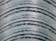
The amount of roughness of the treated surface is affected by a lot of reasons, among which are: the material of the workpiece, the cooling medium, the design and condition of the cutting edge of the tool, cutting modes (first of all, feed and cutting speed) and the rigidity of the "machine - tool - workpiece" system.
-
incorrect tool selection
-
incorrect chip thickness to be removed
-
the cutting speed is incorrectly selected
-
the processing of the material requires the use of a coolant
-
high feed
Recommendations:
-
apply finishing СМП or SMP with a stripping chamfer
-
apply SMP with suitable cutting geometry
-
reduce the feed
-
change, for the most part, increase the cutting speed
-
apply cooling or lubrication (MQL)
-
eliminate the cause of vibrations
-
apply a tool with the possibility of more precise installation and adjustment of the position
-
individual SMPS (with milling)
-
change the thickness of the chip to be removed (change the embedding conditions)
2. Surface unevenness due to vibration

This is a very frequent phenomenon, the main reasons for which include the imbalance of the tool, non-rigid fastening of the workpiece and high values of cutting forces.
-
low rigidity of the "machine – tool – workpiece" system
-
too large chip depth (both axial and radial)
-
runout - poor balance of the workpiece or tool
-
large tool reach
Recommendations:
-
check the reliability of fixing the workpiece
-
check the reliability of fixing the tool
-
reduce the cutting depth
-
apply a tool with a smaller departure
-
adjust the cutting speed
-
reduce chip thickness (change cutting or embedding conditions)
-
change the cutting geometry to the sharpest and most positive (minimize effort
-
cutting), choose another SMP material
-
apply, in the case of milling, a tool with a smaller angle in the plan
3. Burr formation

This phenomenon is very common, but it can not always be prevented. Burr occurs primarily when processing soft steels and plastically deformable materials.
Recommendations:
-
apply SMP with sharp cutting edge
-
apply SMP with positive geometry
-
apply a tool with a smaller angle in the plan
4. Inaccuracy of the size and shape of the workpiece

This phenomenon occurs as a result of a large number of factors, or the properties of the "machine – tool – workpiece" system
Recommendations:
-
choose a SMP with sufficient wear resistance
-
check the reliability of fixing the workpiece
-
check the reliability of fixing the tool (reduce the overhang or eliminate the imbalance)
-
choose the appropriate size of the processing allowance
5. Unacceptable chip shape

The acceptable shape of the chip is currently as important a criterion as the service life of the СМП. The chip crushing process is influenced by: the material of the workpiece, feed, cutting depth, and, of course, the appropriate choice of cutting geometry (chip breaker).
Long (unformed) chips are unacceptable for many reasons, as well as too short - very finely "fragmented" chips are undesirable (this indicates an overload of the cutting edge and the process of vibration).
Recommendations:
-
change feed and cutting depth
-
choose a more suitable geometry
-
change the embedding conditions
General recommendations
- Control of the correct fit of the NSR in the socket.
Before installing with a new SMP or a change of the cutting edge, it is necessary to clean the seat, check its condition — there is no damage to the wedge and the backing plate.
- Control and repair of fastening segments.
It is also important to control the fasteners themselves: the angle lever, screw, tack or clamping wedge. Only undamaged elements should be used for fastening, in case of their replacement, only spare parts that are listed in the catalog of this tool should be used. Regularly lubricate the thread and the conical bearing surface of the screws with grease resistant to elevated temperatures, for example, Molykote G. When mounting or disassembling, use only screwdrivers and keys specified in the catalog and recommended by the tool manufacturer. It is necessary, if necessary, to tighten the screws, using a torque wrench.
- Pinning control.
When fixing the NSR, it is necessary to check its tight fit over the entire support surface and at close range - both in radial and axial directions. Fixed SMPS and tools must always be clean and undamaged.
Sandvik materials were used, Pramet.